When I first started compositing visual effects for 35mm film there was only one log file format – Cineon. Today, virtually every digital cinema camera manufacturer (Arri, RED, Panavision, etc.) plus professional still cameras have the option to export log images. The advantages of log for High Dynamic Range images are becoming increasingly appreciated in the industry and their use is spreading to ever more projects. If you have not yet encountered log footage, you surely will soon. Log is coming for you! In this article, we’ll take a look at the four big advantages of log images, how it achieves them, and finally how to work with them so let’s read on!
1: The Wonders of Log
The primary users of log images are Visual Effects, Digital Intermediate, and tech-savvy photographers working with High Dynamic Range (HDR) images. They come in the form of 10-bit log DPX files, which is a modernized version of the old Cineon log format developed for digitizing 35mm film. While cameras can export log files directly, an adventurous colorist may want to export the camera raw files and convert them to log in post to gain an extra level creative of control. Log images offer four main advantages:
- More dark detail
- Eliminates banding
- Retains highlights
- Smaller file size
In this section, we take a close look at each of these four advantages comparing log images to exporting a Rec. 709. Camera raw files could also be used for dark detail, banding, and highlights but the file sizes will be much larger. In the following sections, we will gain an understanding of what log images are and how they deliver these advantages.
1.1 More Dark Detail

Figure 1 illustrates the difference in retained dark detail between exporting camera footage as Rec. 709 (video) vs. log. In the left image, the shot was exported as Rec. 709 so the shadow dark detail was crushed and clipped upon export. The insert window is a close-up that demonstrates what happens when an attempt is made to increase the dark detail with a gamma adjustment. There was no picture information to begin with so it just stays black. On the right the camera export was log so it retained the dark detail, then the log image was converted to Rec. 709 for the insert window. Because the log image retained the dark detail the conversion to Rec. 709 could be adjusted to reveal it.
1.2 Eliminates Banding
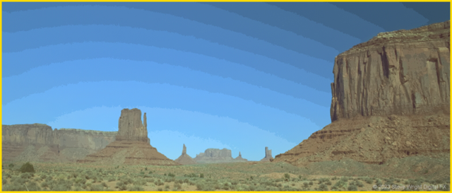
Banding (contouring) occurs when there are too few bits to cover a gradient region like the blue sky in Figure 2. While the entire image may be 8 bits with 256 brightness steps overall, in the sky region for example, there may be only 4 bits available with 16 brightness steps. The 16 steps of brightness spread out over a large, smooth gradient like the sky can exhibit banding.
However, for a 10-bit log image with 1024 steps of brightness, the sky region may have 6 bits available resulting in 64 steps of brightness over the span of the sky. With so many small steps any banding becomes unnoticeable.
1.3 Retain Highlights

Figure 3 illustrates the difference between exporting camera footage as Rec. 709 vs. log for a High Dynamic Range (HDR) image. In the left image, the shot was exported from the camera as Rec. 709 so the flame detail was clipped upon export. The insert window is a close-up that shows the flame is a featureless slab of white. On the right the camera export was log, which has the dynamic range to retain the flame detail, then the log image was given a soft clip to bring the flame down within the range of Rec. 709 before conversion. Not only are the flame’s internal details retained but even the window grids remain visible.
1.4 Smaller File Size
Of all the HDR file formats DPX log files have the smallest file size by around 20%-30%. A 10-bit log DPX file fits all three channels (RGB) into a single 32-bit word resulting in 4 bytes per pixel. And as we shall soon see, it achieves this through the magic of bit allocation without using any compression. A 16-bit linear OpenEXR file requires 16 bits per channel times 3 channels, which means 6 bytes per pixel. A 32-bit float tif file requires 8 bytes per channel times 3 channels for 24 bytes per pixel. Honestly, who uses a 32-bit float tiff file anyway?
2: The Log Image
Log images were developed in 1991 when Kodak needed to digitize 35mm film for the Digital Intermediate process they were developing. Digitized 35mm film has two very large attributes – first, it is High Dynamic Range, and second, they are huge 2k images (2k was huge back then!). Log files store the logarithm of each pixel’s code value, not the code value itself. Linear images store the pixel code values directly and are sampled (digitized) evenly from dark to bright. However, storing the digitized film in a linear file format is not efficient for the reasons revealed here.
2.1 The Trouble with Linear Images
Log files store HDR image data more efficiently than linear files which result in more picture with fewer bits. You see, linear files have a dirty little secret – in fact, two dirty little secrets. First, they waste bits in the brights and second, they are prone to banding in the darks.
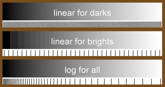
This is all made clear in Figure 4. The top graph linear for darks shows the data bits closely spaced to avoid banding in the darks. However, that creates the problem of the bits being too close together in the brights to be noticed by the eye. If this were an 8-bit tiff (0-255) you could not see the difference between code values 252 and 255, so the 3 bits between them are wasted. Not efficient.
We can fix this easily by spreading the bits out to avoid wasting them in the brights like the linear for brights graph in the middle of Figure 4. However, that introduces banding in the darks. Notice that you can see the banding on the left side of that graph but the right side seems to smooth out even though the bits are spaced equally throughout. The lack of banding on the right is because the eye becomes less sensitive in the brights so we do not see the banding there anymore. But we now have banding in the darks. Not good.
The log for all graph at the bottom of Figure 4 shows how log neatly solves both problems by allocating the bits so they are closely spaced in the darks to avoid banding but widely spaced in the highlights to avoid wasting bits. With the closely spaced bits in the darks, there is much more shadow detail available that can be fearlessly exploited without introducing banding.
♦ If you would like to learn more about ‘linear images’ then check out my webinar on Working in Linear!
2.2 The Log LUT
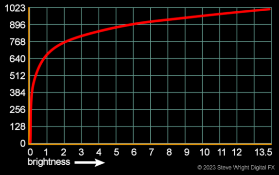
So variable bit allocation is clever and good, but exactly how is it done? With a log LUT, of course, like the one in Figure 5, which represents the Cineon (DPX) log LUT. Because it is a 10-bit file the data range is 0-1023 so the max code value on the Y axis is 1023 and the maximum brightness is 13.5 on the X axis. Of course, the vast majority of the picture brightness will range between 0 and 1.0 with everything above 1.0 allocated to highlights. This is a generous highlight range that will do fine for fireplaces, explosions, village torches, and like that. In order to actually get a brightness greater than 13.5 you would pretty much have to shoot directly into the sun.
For work in Visual Effects, the log images must first be linearized (de-logged) with an inverse log LUT. You should know that today there is a veritable zoo of log LUTs out there each tuned to the camera that generated the image – REDlog, Panalog, Viperlog, AlexaV3LogC, etc. The disturbing screenshot in Figure 6 shows the zoo of log LUTs available today in the Visual Effects software Nuke (my app). One can only imagine how many there will be tomorrow.
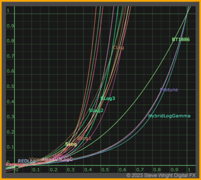
There are two critical issues with these camera log LUTs. First, you must be absolutely certain to use the right one. All too often footage is dropped off without camera logs and the Visual Effects artist has to figure out which camera log LUT to use to linearize the data. Using the wrong log LUT will introduce subtle color shifts that could take hours to troubleshoot. The second issue is that some log LUTs produce negative code values. When working with these negative code values they should be preserved all the way to the final output without clipping. For that, you have to be working in floating point.
2.3 Bit Allocation
Bit allocation, or how the code values get distributed, is shown in Figure 7 starting on the left with the camera’s linear image sensor. They produce linear image data with a bit depth of anywhere from 10 to 16 bits depending on the camera model. This linear data goes through the camera’s log LUT to be re-sampled (re-digitized) upon export to produce the log export file in the center of Figure 7. Notice how the code values are clustered close together in the darks and then spread out as it moves up into the highlights.
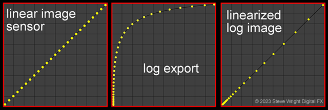
When log images are used for Visual Effects they must first be linearized (de-logged) with an inverse log LUT to produce the linearized log image on the right in Figure 7 above. Notice how the bit allocation now has bits concentrated in the darks and spreading out in the highlights like the log for all graph in Figure 4. Visual Effects may now be done on the shot without worrying about introducing banding. Colorists in Digital Intermediate and tech-savvy photographers will work directly with the log files because they retain the High Dynamic Range and the results look more filmic.
You may wonder why we don’t just skip converting them to linear and do the Visual Effects with the log images. Because the math operations for image manipulation must be done on linear images or the results will be wrong. The real world is linear, CG calculations are linear, and image processing is linear. It’s our vision that is non-linear and log helps to bridge that difference without wasting bits.
3: The Log Workflow
Hopefully, by now you have a clear notion of what log images are and how they work so we can now consider the details of the log workflow. Some will mistakenly refer to this as “shooting in log” but as we shall see there is only shooting in linear and then converting to log. Of course, exporting Rec. 709 directly from the camera is faster and cheaper. If you export log then it requires the added step of supervising the conversion to Rec. 709, but the payoff is a whole new level of creative control. We will use Figure 8 to trace the data path from the linear image captured by the camera to the log export and then out to a Rec. 709 HDTV delivery.
We start with the linear graph on the left in Figure 8 which represents the linear capture of all digital cameras. As we have seen, the definition of linear data is a one-to-one relationship between the code values and pixel brightness. The code values are equally spaced from dark to light and go off to some upper limit that is different for each camera, hence the faded graph edges. The inset photo shows a linear image as it would appear without a display LUT.
For a log export, the linear image is converted to log with the camera’s log LUT as it exports the data. Alternately, the linear data can be exported and then converted to log in post by the colorist giving the colorist another degree of freedom to adjust the color during conversion. The Cineon log curve shows three key reference data points indicated by the cyan arrows. Linear code value (cv) 13.5 maps to log code value 1023, linear cv 1.0 maps to log 685, and linear cv 0 maps to log 95. The reason the linear cv 0 maps to log 95 is to leave some data “footroom” for negative noise (grain) which is indicated by the ghosted -1 below the zero at the bottom of the Y axis.
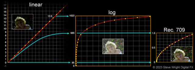
The log graph in the center of Figure 8 illustrates how the bits are spaced out when it is re-sampled (digitized) to 10 bits in order to write the log image to disk. The code values are spaced very close together in the darks and spread out in the brights. This results in very small changes in brightness between code values in the darks, which is what we need to prevent banding. It also results in larger and larger brightness steps as you follow the log curve up into the highlights, just like we want for our non-linear human vision.
The log graph in the center of Figure 8 shows the Cineaon 10-bit log DPX curve with the CVs ranging from 0 to 1023 on the Y axis. Code values 95 and 685 are marked as they are the reference points for 0 black and 1.0 white when converted to Rec. 709. Code values above 685 are used for highlights, and while not displayable in Rec. 709, are highly prized for digital cinema. Note that the maximum code value is 1023 which maps to the linear code value of 13.5, the brightest pixel value that Cineon/DPX log images can store. Other log LUTs will have a different maximum code value, but they all have a maximum. The inset photo shows the familiar low-contrast log image as it would appear without a display LUT.
The Rec. 709 graph on the right of Figure 8 is the gamma-corrected linear image produced by converting the log code values from 95 to 685 to HDTV. The log code values above 685 are highlights that exceed the headroom available in HDTV but are quite useful for digital cinema or even back to 35mm film, should anyone ever want to do that. The log code values below 95 are not utilized for HDTV because they are simply black grain noise.
Log code values 95 to 685 are the “normal” range used to convert log to Rec. 709 but this is where the great latitude of log enters the picture (pun intended). The output image can be “pre-graded” during the conversion from log to linear rather like developing a print from a negative. What portion of the log curve that is converted to Rec. 709 can be dialed up or down changing the exposure. Also, the log black and white points can be moved closer together or further apart to lower or raise the contrast. These are not color grades on the Rec. 709 output as that can degrade the image data. They are instead tweaks to the range of log code values used to convert to Rec. 709 in the first place to produce a balanced, well-exposed shot before starting any color grading.
3.1 Color Grading Log vs. Linear
You cannot use the same math operations on logarithmic and linear data. For example, to increase the exposure of a log image you add a constant to the RGB values with a “plus” operation. To increase the exposure of a linear image you scale the RGB values with a “gain” operation. Taking a Cineon (DPX) log image as a case in point, to double the exposure add 0.088 to the log image. After the log image has been linearized (de-logged) you would achieve the same results with a gain of 1.34 on the linear image before it gets the Rec. 709 gamma correction.
Conclusion
While log images have been around ever since digitized 35mm film they have now become pervasive in cinematography since all digital cinema camera manufacturers offer them. We puzzle over the strange low contrast blown-out images that they produce and wonder why we need them, and more importantly, how to work with them. As it turns out, we can think of the log image as a “negative” from which we develop a Rec. 709 “print” for display. And during that exposure process, the log image offers several artistic and quality advantages compared to working with the final Rec. 709.
Be sure to sign up for our newsletter so that you don’t miss informative articles like this one!
Until next time, Comp On!
Steve
