The first article, “Color Spaces of the VFX Pipeline” traced an overview of the color path from the original scene in the real world through capture with a camera, storage space, workspace, to display space. Part 2 in the series, expanded on the subject of color in the real world. Part 3 expanded on the topic of cameras and how they perceive the real world and their effect on the images they capture for our visual effects. Part 4 expanded on the subject of how we store image data to avoid damaging those images and to future-proof feature films. Part 5 expands on the subject of the impact of choosing a workspace and how it affects the quality of our images. Parts 1-3 and previously archived articles may be accessed by becoming an FX Ecademy member.
Introduction
In Part 4, Storage Space, we explored the options and virtues of different image file formats for storing our VFX images. Here we move to the next stage of the production pipeline for our VFX shots by asking what happens when our thoughtfully stored images are loaded from disk into the “workspace” which is the color space where all of the image processing and color correction operations will be done. This will serve as a guide towards choosing a workspace that will protect the quality of your work and provide future-proofing[1]. Most apps will give you a choice of workspaces with Nuke being the rare exception. Nuke’s workspace is linear light space unless you know how to trick it into working in other color spaces such as sRGB or Rec. 709. Note that Nuke’s linear light space is not a true color space, while sRGB and Rec. 709 are. More about that in a bit.
Beyond selecting the color space you are going to work in, additional considerations are what precision you will work in (8-bits, 16-bits, etc.) and the math – integer or float (floating-point). The following sections explore and explain each of these three issues so that you may choose wisely for your own production shots. Since you must choose a color space to work in it might be useful to know what a color space actually is.
[1] Future-proofing is to produce a production job at sufficiently high resolution and color dynamic range that it will be able to take full advantage of future display devices.
A word about color science here. Color science is a formidable topic with complex components of optics, color theory, signal processing, and the wildly complex human visual system. So the color science in this article is, of necessity, over-simplified in order to tell a story that is actually useful to visual effects artists. Color scientists are advised to avert their eyes!
1: Color Models vs. Color Spaces
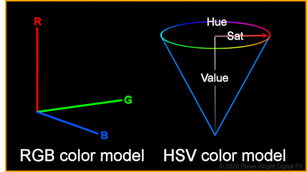
A color model is the little brother to a color space. The color model is incomplete because it only describes the axis of the color space coordinate system like the illustrations here for the RGB and HSV color models.
A true-color space needs two more parameters, namely the primary chromaticities and the transfer function. Primary chromaticities are the technical specs for the specific color of the three primary colors red, green, and blue, and are specified by their locations within the CIE Chromaticity diagram.
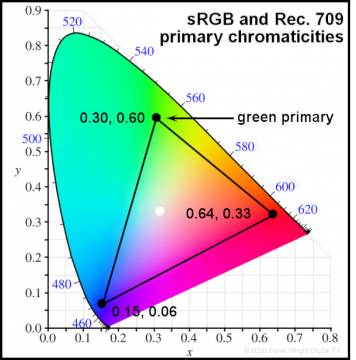
How the primary colors are specified is illustrated here. The CIE Chromaticity diagram is a two-dimensional graph of the entire range of colors visible to the human eye. Any color can be described with great precision by its x,y location within this diagram. For example, the sRGB and Rec. 709 green primary is marked by the black dot at x = 0.30, y = 0.60. This is how the chromaticity (color) of the three primary colors of an RGB system is described – hence primary chromaticities.
The black dots mark the location of the primaries in the diagram and when those dots are connected they form a triangle that outlines all the possible colors that the color space can make which is known as the gamut of that color space. The white dot near the center of the gamut marks the white point that defines what is “white” for that color space. The gamut of a color space is a very important parameter and affects much of our art. One example is creating visual effects that are out of gamut for a TV display which is why some software has the zebra pattern to mark out of gamut pixels.
So far we have seen that the primary chromaticities, gamut, and white points for the sRGB and Rec. 709 color spaces are identical. So what’s the difference between them? Why, the transfer function, of course. And you thought we had forgotten about the transfer function. No such luck.
So what is the transfer function then? It is the mathematical description of the relationship between the RGB color model code values and the actual RGB values produced by the display device. In its first approximation, we can refer to it as the gamma of the color space. For sRGB, the gamma is 2.2 and for Rec. 709 it is 2.4. So if it is just the gamma then why do we have to lard it up with polysyllabic gobbledygook like “transfer function”? Because, of course, there is more to it than just a simple gamma value.
Here’s the story – if we were to use just a gamma of, say, 2.2 as the transfer function then the curve would look like the illustration here. The problem with using a gamma curve alone is that at the head of the curve at 0,0 it is vertical which means the slope of the curve at that point is infinite. An infinite slope is a fatal problem for real devices like video signal amplifiers because it means the signal is being scaled by infinity. As you trace up the curve in the immediate vicinity of 0,0 the slope calms down to a billion, then a million, then a thousand. These are utterly impractical numbers for real devices because the signal down there is mostly noise so the noise is being scaled up by a billion. Not cool.
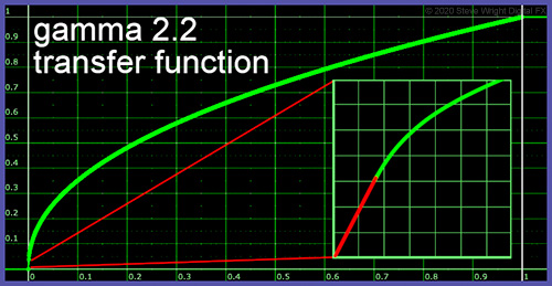
The solution to this pesky problem is shown in the magnified inset window on the right. The engineers simply patched in a short straight line (red) with a reasonable slope that starts at 0,0 and goes to the point where it is tangential to the gamma curve (green) where the actual gamma curve takes over from there on out. To close the conversation on color models and color spaces here is a useful summary list:
Important Color Models:
RGB, CMYK, CIE, YUV, HSL/HSV/HSB/HSI
Important Color Spaces:
sRGB, Rec. 709, Rec. 2020, Adobe RGB, ProPhoto, DCI-P3, ACES, CIELAB
2: Integer vs. Float
A key decision point for choosing your workspace is whether to go with integer or float (floating-point) math. Integer math is, for example, where 8 bits range from 0 to 255, which equates to 0 to 1.0 in float. Interestingly, 16-bit integer math which ranges from 0 to 65,535 also equates to 0 to 1.0, so while there is a great increase in precision to avoid banding problems there is no increase in dynamic range. Rec. 709 video also supports a 10-bit option ranging from 0 to 1023, but that too equates to 0 to 1.0. Common apps using integer math would be Photoshop and After Effects. Integer math may be adequate for broadcast and web applications, but it falls short when it comes to feature film work or future-proofing your precious project.
For the high-end work of feature film, floating-point math is an absolute requirement. Floating-point math solves the precision problem to avoid image degradation from multiple image processing operations and it also solves the dynamic range problem as it comfortably handles code values well above 1.0. In an all-float pipeline, you might save your image data as .exr files for example which are 16-bit half-float that are “promoted” to 32-bit float when imported into the computer. The logic here is that storing the image as 16-bit half-float retains far more data about the image than you will ever need, then promoting it to 32-bit for processing adds so much more precision that you will never visibly degrade your images.

I often illustrate the image degradation problem with integer math with the above demo. I take an 8-bit tiff image in Photoshop and scale the RGB values down by a factor of 16 to nearly black, then restore it to its original brightness by the same factor of 16. Photoshop works in integer math so the image erupts with hideous banding artifacts and the background blacks are crushed to a single value.
I then repeat the demo with Nuke’s floating-point math using the same 8-bit tiff image, but this time I scale the RGB values down by one million, then restore it by scaling it back up by one million. The original 8-bit image is restored perfectly with no visible degradation. In actuality, there are microscopic round-off errors in the restored image but they are so small (in this case 21 parts in a million) as to be utterly invisible. Such is the power of floating-point math.
So if float is so good why do we even have integer math? In a word, legacy. In the early days of computer graphics, the computers were slow so they used integer math because it was much faster than float. Many software apps were first written in those days so they have integer math embedded in their software. Today’s machines are much faster at floating-point math so the speed advantage of the integer is virtually gone. However, rewriting that legacy software to change it from integer to float would be a massive architectural change to the software and expensive to do. So they plod along with their integer math because it works well enough for the limited applications of the web and video.
3: Linear vs. Gamma Corrected
This is a truly tragic tale. On the one hand, image processing math wants to be done in linear, while most of our beloved file formats like tiff and ProRes with color spaces sRGB and Rec. 709 are non-linear. So let’s take a step back for a moment to become clear on what it means for an image to be linear.
Simply put, linear means there is a 1:1 relationship between the code value for the brightness of a pixel and its actual brightness on the display device’s screen. For example, a code value of 0.5 would result in a 50% brightness on the screen. In this linear world if the code value is doubled from 0.5 to 1.0 then the brightness would be doubled from 50% to 100%. Simple enough. But that is not how early display devices worked.
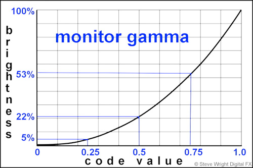
Due to the infernal physics of the CRTs (Cathode Ray Tubes) that were used for early TV screens, doubling the input signal to the CRT did not double the brightness. The diagram here shows what happens. Code value 0.5 only elicits a brightness of 22%. Doubling that to 1.0 the brightness jumps from 22% to 100%, nearly 5 times brighter. Very non-linear. Checking the code value vs. brightness at a couple of other points along the curve shows that the relationship between the code values and brightness is constantly changing, and the mathematical rule for that change is gamma.
The nature of this intrinsic gamma curve in the CRT was to seriously darken the original image. This is illustrated below where the original image is depicted on an early TV with a CRT and labeled gamma darkened. The engineering workaround was to incorporate a compensating gamma correction in every video camera that adds the opposite gamma curve in order to seriously brighten the image. The two gamma curves offset each other so that the displayed image looks correct. So the tragic tale here is that every image still has a gamma correction baked into it which means it is non-linear.
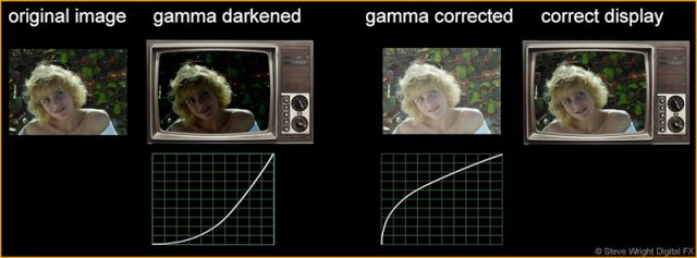
But we don’t use CRT’s anymore, so why are we still doing this? When the modern flat-panel displays were developed it was decided to add a factory gamma curve to match the old CRTs so that the billions of existing images and videos will look right on the new displays. This is why these display spaces are gamma-corrected and non-linear. So the next question is – why do we care?
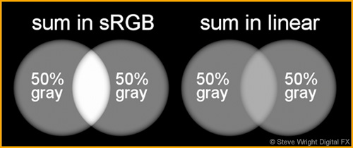
We care because all image processing and color correction operations want to be done on linear images for the results to be absolutely correct. A stark example of the difference between image processing in, say sRGB vs. linear is shown here. Two 50% gray patches are simply summed together, one summed in sRGB and the other in linear. You can see the huge difference between the overlapped regions.
Now here is the punch line – the “sum in linear” illustration is in fact what you would see in the real world if two spotlights were overlapped like this. The overlapped region would appear about 18% brighter than each spotlight, not the 50% brighter result for the “sum in sRGB”. This little summing demo is just the tip of the linear iceberg. There is a long list of other consequences of not working in linear, though not as dramatic.
♦ If you would like to learn more about working with linear images check out my webinar Working in Linear!
Truth be told, you can certainly work successfully with gamma-corrected images even if it’s not quite right. In fact, most of our work is done this way because image processing and color correction operations still look reasonable. But for feature film and CGI work “looking reasonable” is not good enough. To work at this level it has to be right. And the only way for it to truly be right is to work in linear.
With our new-found knowledge of what makes a color space we can now place the linear workflow in its proper perspective. While its color model is defined (RGB) as well as its transfer function (linear) it is not a true color space simply because it does not have any defined primary chromaticities. It simply adopts the color primary assumptions of whatever image you linearize. While it is an essential workspace, it is technically not a true color space in its own right. Linear is the preferable workspace regardless of whether the color space of the input images is sRGB, Rec. 709, DCI-P3, or the awesome new Rec. 2020 – which will be covered in detail in Part 6 “Display Space”.
Armed with the knowledge of what a color space is plus an understanding of the difference between integer and float as well as linear and gamma-corrected workspaces, we are now equipped to tackle the question of the moment – what should your workspace be?
4: Working in Display Space
The over-arching principle of choosing the right workspace is that it should be “larger” than the display space of your final deliverable to avoid clipping and degrading your work. However, as we now understand, a great deal of visual effects and color-correcting for web and broadcast is done in the display space. So what are we to think of that?
Working in a display space means to work in the same color space as the intended display device. If you are working on graphics intended for display on a workstation monitor (an sRGB display device) then you would load images that are in sRGB color space into memory without converting them in any way. If you are working on a video project intended for broadcast then your images will be in Rec. 709. They too are simply loaded into memory without conversion and are properly viewed with a broadcast monitor which is a Rec. 709 display device. If your workstation does not have a broadcast monitor you can fudge things with a Rec. 709 LUT on your viewer that will make a fairly close approximation. This is how the vast majority of non-feature film work is done and it works reasonably well.
However, working in display space introduces several problems that you will need to properly manage. The first problem is clipping. A ‘display space’ is spec’d out to match a given display device – sRGB for monitors, Rec. 709 for HDTV – so there is no need for any image data to exceed code value 1.0, the max for those display devices. But in VFX image processing and color-correcting, the image data can easily go above 1.0. and below zero. If left unattended the excessive code values will simply be clipped to zero and 1.0 which is decidedly unattractive. Most image processing systems, therefore, have a “zebra” display option to mark illegal pixels with a crosshatch pattern to alert the artist. The first solution is to avoid clipping altogether by turning on your zebra patterns and watch your images carefully to avoid exceeding 1.0 by choosing appropriate image processing operations. The second solution is to blast away on the shot without worrying about clipping, then introduce a soft clip to blend the hard edges of any clipped regions as the last operation. At least the soft-clipped regions won’t look too bad.
The second problem is banding can be introduced if using integer math. However, most systems support the ability to promote an 8 or 16-bit image to float internally, or may even do it automagically for you. This is highly recommended as we saw above the many evils that can befall an artist working in integer. The third problem is the most insidious of all – display spaces are gamma-corrected so are not linear, and as we saw above, quality image processing math wants to be done in linear. Having said all this, you can safely work in display space if you keep the above caveats in mind and you do not need to future-proof your work.
5: Working in Linear
As we saw in the overlapping spotlight illustration above, if it has to be right it has to be linear. Linear is in fact how the real world works, and because of that physical fact, all 3D renders are done in linear because 3D is a simulation of the real world. As we learned above, VFX image processing operations and color corrections must also be done in linear for the results to be truly correct. A corollary to working in linear is that the workspace math must be floating-point, and because it is floating-point it will therefore be high dynamic range and support negative code values. These three attributes – linear, float, and HDR – are absolutely required to maintain maximum quality and to future-proof a project.
The workflow goes like this – images are loaded from disk in whatever color space and format they may be, including log, then linearized prior to all operations. Once all of the image processing is complete, the linear images are then converted to the destination color space and written to disk in whatever file format the project requires. Note that in the linear workflow the output color space need not be the same as the input. The single exception to this workflow is OpenEXR files which, by definition, are already linear so they just load and go without any color space conversion. When writing to disk they get no color space conversion as they are already linear and are simply written out in the .exr file format. Using OpenEXR throughout the pipeline is the highest quality that preserves and protects your project for future-proofing. A common second choice is to write them out as log images such as DPX as it is a high-quality format that takes a bit less disk space than OpenEXR but not high enough quality to be considered future-proofed.

Note that when images are linearized they become unviewable as shown above. As we learned, the workstation will have a monitor with a built-in gamma that seriously darkens the display which is why the images have a gamma correction baked in to compensate. Once they are linearized and loose that gamma correction they become hopelessly dark and impossible to work with visually. In order to see the work on the monitor, there needs to be a viewer LUT that converts the linear data to the monitor’s color space on the fly leaving the original image’s linear data untouched. So you work in linear but view in sRGB (for example).
♦ If you would like to learn more about premultiplied images check out my webinar Premultiply and Unpremultiply Demystified!
5: Working in ACES (Academy Color Encoding Specification)
While working in linear may sound like the end-all for top quality work, there is actually one more step up that one may take, and that is to work in the ACES color space. The story is that linear is almost the ideal workspace, but it has one shortcoming. When cameras photograph a scene they bake the camera’s attributes into their captured images. This is why the same scene captured by several different camera models will look slightly different. One camera may be slightly more sensitive in the reds, another may record less detail in the darks.
What ACES does is remove the camera’s attributes from the image data so that it essentially represents the light from the original scene. This is what is called scene-referred data. It is linear, float, and HDR just like the linear workspace above, but with the added distinction of representing the original scene without any camera bias. Further, the linear data is imported into the ACES workspace which has a huge gamut far in excess of the human visual system or any physically realizable display device today or in the future. It is the ultimate in future-proofing. ACES is rapidly gaining acceptance in the world of visual effects and Digital Intermediate and it won’t be long before you will have to confront it, so let’s pause for a closer look.
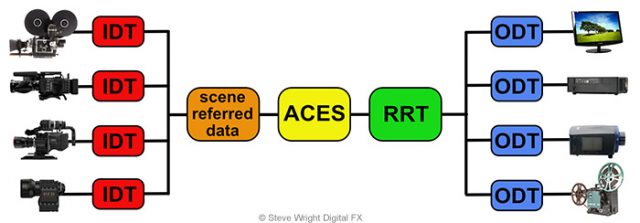
The above diagram illustrates the ACES workflow. On the far left are various capture devices. Each manufacturer publishes a profile of the camera describing its response characteristics. The IDT (Input Device Transform) uses that information to back out the camera’s “fingerprint” to produce the scene-referred data. The scene-referred data is then imported into the ACES workspace (linear, float, and HDR) for all image processing and color correcting. The color corrected data then goes through the RRT (Reference Rendering Transform) which is a LUT that imparts a “film look” to the ACES data as this is considered the gold standard for the display of images and represents a starting point for color correction. From there it goes to an ODT (Output Display Transform) which converts it to a display device’s color space and adjusts the data to make it visually consistent regardless of which display device is used. Within the limits of each display device, the image will now look the same no matter what display device is used.
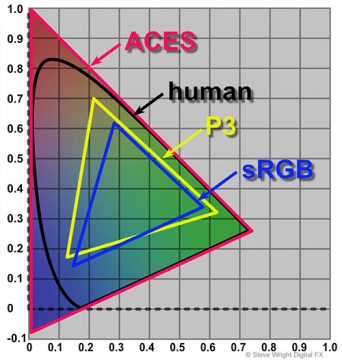
The ACES gamut shown here is deliberately gigantic. All other color space gamuts fit within it, including the human visual system. Since it incorporates all possible color space gamuts it is the ultimate future-proofing tool. A job saved out in ACES can be re-opened years later and re-rendered for a new display device that has not been invented yet because the ACES data will still incorporate it. Another virtue of ACES is the ability to do gamut and tone-mapping to multiple color spaces. You can tone map from a larger to a smaller color space – for example from ACES to P3 – by artfully compressing the larger gamut to fit within the smaller. However, going the other way from smaller to larger such as from sRGB to P3 means your original image is missing the color information for the larger gamut. Colorists will often just “park” the sRGB into the larger P3 (for example) and not try to remap it. And of courses, OpenEXR is ideal for saving ACES projects.
Conclusion
The basis for choosing a particular workspace for your VFX work is that it is “larger” than the final deliverable color space. If it is not, problems like clipping and image processing artifacts will degrade the final product. However, we can still do good work using display spaces such as sRGB or Rec. 709 as the workspace but the artist will have to be on guard to protect the work from the problems cited above like clipping plus the work will not be future-proofed.
For high-end work like feature films the workspace must be linear, float, and HDR. While this will protect the work from clipping and processing artifacts and offers some future-proofing, it is not the ultimate solution. For the ultimate in work quality and future-proofing, the ACES workflow is recommended!
In our next newsletter, Color Spaces of the VFX Pipeline Part 6 –
Display Space, looks at the question of what happens when the image data gets displayed on a monitor or projected on a screen. We will be looking at what kind of color range different display devices support, their dynamic range, bit depth, and the file formats that may be used with them.
Be sure to sign up for our newsletter so that you don’t miss informative articles like this one!
Until next time, Comp On!
Steve


0 Comments